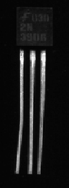
Troubleshooting - Testing Transistors
   Pictured above are the 3 main transistor types used on the videocipher circuit board. The MPS2907A & 2N3906 are PNP type transistors and the 2N3904 is an NPN type transistor.
When testing these 2 types of transistors the procedures are the same, just the test lead polarity is reversed.
Below is the test procedure for testing NPN type transistors.
* Place your DMM into the diode test mode, this mode provides sufficient voltage to forward-bias & reverse-bias a transistor junction.
Hold the transistor with the flat portion with the lettering on it facing you.
In order to continue you will need to know the pin out of the 3 transistors, here they are:
MPS2907A 2N3904 2N3906
All 3 transistor types are configured as: Emitter Base Collector
This meaning, the pin farthest to the LEFT is the EMITTER the MIDDLE pin is the BASE and the pin farthest to the right is the COLLECTOR
NOTE NOTE NOTE NOTE NOTE NOTE NOTE NOTE NOTE NOTE NOTE
PLEASE NOTE, THE FOLLOWING PROCEDURE IS FOR TESTING NPN TRANSISTORS (2N3904), if you are testing PNP transistors all lead's should be reversed when taking measurements
NOTE NOTE NOTE NOTE NOTE NOTE NOTE NOTE NOTE NOTE NOTE
Now that you know the pin outs let's start testing.
- Place the NEGATIVE lead from your DMM and place it on the EMITTER of the transistor
- Next, place the POSITIVE lead of the DMM on the BASE of the transistor
*** Result *** You Should Be measuring About 0.70 Volts or 700 mV
This is known as forward-bias testing the base & emitter junction of the transistor.
- Next, Reverse the leads by placing the POSITIVE lead from the DMM on the EMITTER now and the NEGATIVE lead from the DMM to the BASE
*** Result *** You Should Be Measuring About 2.60 Volts
This is known as reverse-bias testing the base & emitter junction of the transistor.
Now let's forward bias test the Base & Collector Junction
- Start by placing the POSITIVE lead frmo the DMM on the BASE
- Then place the NEGATIVE lead from the DMM on the COLLECTOR
*** Result *** You Should Be Measuring About 0.7 Volts or 700mV
- Next, Reverse the leads on the transistor as follows:
- Place the NEGATIVE lead from the DMM on the BASE
- Pleace the POSITIVE lead from the DMM on the COLLECTOR
*** Result *** You Should Be Measuring About 2.60 Volts
Here are some faults which may occur and the resulting measurements
NOTE: Your DMM Must ALWAYS Be In The Diode Test Mode When Making These Measurements
*** POSSIBLE FAULTS & RESULTS ***
PROBLEM: When measuring across the BASE & COLLECTOR junction I got about 2.60 volts and not the specified 0.7 volts (700mv), what is wrong? (Note: Positive lead is on base & negative lead is on collector)
ANSWER: The Base & Collector Junction Is OPEN CIRCUIT, Replace Component.
PROBLEM: When reverse-bias testing the BASE & COLLECTOR junction I measured 2.60 volts and not the required 0.7 volts (700mV), what is wrong? (Note: Negative lead is on the BASE and the positive lead is on the COLLECTOR)
ANSWER: The Base & Collector Junction is OPEN CIRCUIT, Replace Component.
PROBLEM: When measuring across the BASE & COLLECTOR I get 0.00 volts, what is wrong? (Note: Negative lead is on COLLECTOR and positive lead is on the BASE)
ANSWER: Reverse the leads as when reverse-bias testing and if this measurement remains the same (0.00 volts) the BASE & COLLECTOR are Short Circuit, Replace Component.
> Go BACK To The VCII Troubleshooting Menu <
|


